|
| |
 |
Basic Dynamic Load Rating (C)
This term is arrived at based on an evaluation of a number of identical linear systems individually run in the same conditions, if 90% of them can run with the load ( with a constant value in a constant direction ) for a distance of 50 km without damage caused by rolling fatigue. This is the basis of the rating.
Allowable Static Moment (M)
This term defines the allowable limit value of static moment load, with reference to the amount of permanent deformation similar to that used for evaluation of basic rated load (Co).
Static Safety Factor (fs)
This factor is used based on the application condition as shown in Table 1.
| Table 1. Stactic Safety Factors |
| |
Condition of use |
Low limit of fs |
When the shaft has less deflection and shock |
1 to 2 |
When elastic deformation should be considered with respect to pinch load |
2 to 4 |
When the equipment is subject to vibration and impacts |
3 to 5 |
|
Basic Static Load Rating (Co)
This term defines a static load such that, at the contacting position where the maximum stress is exercised, the sum of the permanent deformation of the rolling elements and that of the rolling plane is 0.0001 time of the diameter of the rolling elements.
Rating Life of the Lineat System
As long as the linear system reciprocates while being loaded, continuous stress acts on the linear system to cause flaking on the rolling bodies and planes because of material fatigue. The travelling distance of linear system until the fist flaking occurs is called the life of the systems. The life of the system varies even for the systems of the same dimenstions, structure, material, heat treatment and processing method, when used in the same conditions. This variation is brought about from the essential variations in the material fatigue itself. The rating life defined bellow is used as an index for the life expectancy of the linear system.
Rating Life (L)
Rating life is the total travelling distance that 90% of a group of systems of the same size can reach without causing any flaking when they operate under the same conditions.
The rating life can be obtained from the following equation with the basic dynamic load rating and the load on the linear system:
For ball type: |
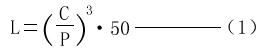 |
| L:Rating life (km) C:Basic dynamic load rating (N) P:Load (N) |
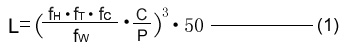
Consideration and influence of vibration impact loads and distribution of load should be taken into account when designing a linear motion system, It is difficult to calculate the actual load. The rating life is also affected by the operating temperature. In these conditions, the expression(1) is arranged as follows:
For ball type: |
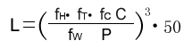 |
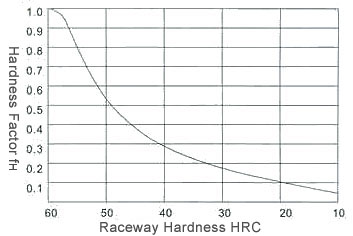
L:Rating lift (km) fh:Hardness factor (See Fig. 1)
C:Basic dynamic load rating (N)
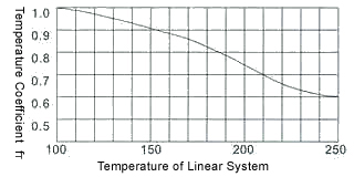
FT:Temperature coefficient (See Fig. 2) P:Load (N)
Fc:Contact coefficient (See Table 2)
Fw:Load coefficient (See Table 3) |
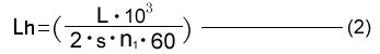
The rating life in hours can be calculated by obtaining the travelling distance per unit time. The rating life in hours can be obtained from the following expression when the stroke length and the number of strokes are constant:
|
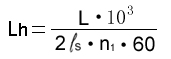 |
Lh:Rating life in hours (hr)
 :Stroke length (m) :Stroke length (m)
L :Rating life (km)
n1:No. of strokes per minute (cpm) |
Hardness Factor (fH)
The shaft must be sufficiently hardened when a linear bearing is used. If not properly hardened, permissible load is lowered and the life of the bearing will be shortened.
Temperature Coefficient (fr)
If the temperature of the linear system exceeds 100℃, hardness of the linear system and the shaft lowers to decrease the permissible load compared to that of the linear system used at room temperature. As a result, the abnormal temperature rise shortens the rating life.
| Fig. 2 Temperature Coefficient |
Contact Coeffcient (fc)
Generally two or more linear bearings are used on one shaft. Thus, the load on each linear system differs depending on each processing accuracy. Because the linear bearings are not loaded equally, the number of linear bearings per shaft changes the permissible load off the system.
Table 2 Contact Coefficient
| |
Number of linear systemsper shaft |
Contact coefficient fc |
1 |
1.00 |
2 |
0.81 |
3 |
0.72 |
4 |
0.66 |
5 |
0.61 |
|
Load Coefficient (fw)
When calculating the load on the linear system, it is necessary to accurately obtain object weight, inertial force based on motion speed, moment load, and each transition as time passes. However, it is difficult to calculate those values accurately because reciprocating motion involves the repetition of start and stop as well as vibration and impact. A more practical approach is to obtain the load coefficient by taking the actual operating conditions into account.
Table 3 Load Coefficient
| |
Operating Conditionss |
Fw |
Operation at low speed (15m/min.or less) without impulsive shock from outside |
1.0 to 1.5 |
Operation at intermediate speed (60m/min.or less) without impulsive shock |
1.5 to 2.0 |
Operation at high speed (over 60m/min.) With impulsive shock from outside |
2.0 to 3.5 |
|
The static frictional resistance of the IN'S linear system is so low as to be only slightly different from the kinetic frictional resistance, enabling smooth linear movement from low to high speeds. In general, the frictional resistance is expressed by the following equation.
|
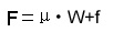 |
F:Frictional resistance μ:Coefficient of friction
W:Load weight f:Sealing resistance |
The frictional resistance of each IN'S linear system depends on the model, load weight, speed, and lubricant. The sealing resistance depends on the lip interference and lubricant, regardless of the load weight. The sealing resistance of one linear system is about 200 to 500 gf. The coefficient of friction depends on the load weight, moment load, and preload. Table 6 shows the coefficient of kinetic friction of each type of linear system which has been installed and lubricated properly and applied with normal load (P/C=0.2)
Table 5 Coefficient of Linear System Friction (μ)
| |
Linear System Type |
Models |
Coefficient of Friction ( μ) |
Linear bearing |
SM KB SW |
0.002 to 0.003 |
|
| Ambient Working Temperature |
The ambient working temperature range for each IN'S linear system depends on the model. Consult IN'S on use outside the recommended temperature range.
Temperature conversion equation
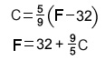
Table 6 Ambient Working Temperature
| |
Linear System Type |
Models |
Ambient Working Temperature |
Linear bearing |
SM KB SW |
-20 to 80℃ |
Linear bearing |
SMG KBG SWG |
-20 to 110℃ |
|
| Lubrication and Dust Prevention |
Using IN'S linear systems without lubrication increases the abrasion of the rolling elements, shortening the life span. The IN'S linear systems therefore require appropriate lubrication. For lubrication IN'S recommends turbine oil conforming to ISO Standards G32 to G68 or lithium base soap grease No.1. Some IN'S linear systems are sealed to block dust out and seal lubricant in. If used in a harsh or corrosive environment, however, apply a protective cover to the part involving linear motion.
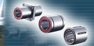
・ The IN'S linear bearing consists of an outer cylinder, ball retainer, balls and two end rings. The ball retainer which holds the balls in the recirculating trucks in held inside the outer cylinder by end rings.
・ Those parts are assembled to optimize their required functions.
・The outer cylinder is maintained sufficient hardness by heat treatment,therefore if ensures the bearing projected travel life and satisfactory durability.
・ The ball retainer is made from steel or synthetics resin. The steel retainer has high rigidity, obtained by heat treat meant.
The synthetics resin retainer can reduce running noise. The user can select the optimum type for meeting the user's service conditions.
1.High Precision and Rigidity
The IN'S linear bearing is produced from a solid steel outer cylinder and incorporates an industrial strength resin retainer.
2.Ease of Assembly
The standard type of IN'S linear bearing can be loaded from any direction. Precision control is possible using only the shaft supporter, and the mounting surface can be machined easily.
3.Ease of Replacement
IN'S linear bearings of each type are completely interchangeable because of their standardized dimensions and strict precision control.Replacement because of wear or damage is therefore easy and accurate.
4.Variety of Types
IN'S offers a full line of linear bearing:the standard, integral single-retainer closed type, the clearance adjustable type and the open types. The user can choose from among these according to the application requirements to be met.
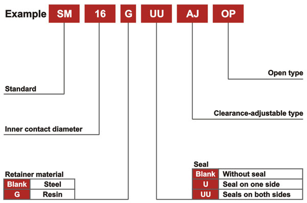
| Type and linear bearing Number |
Note that precision of inscribed circle diameters and outside diameters for the clearance adjustable type (…-AJ) and the open type (…-OP) indicates the value obtained before the corresponding type is subjected to cutting process.
| Load Rating and life Expectancy |
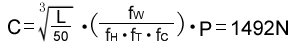
The lift (L) of a linear bearing can be obtained from the following equation with the basic dynamic load rating and the load applied to the bush:
|
 |
L: Rated life(km) fH: Hardness factor(See page5)
C: Basic dynamic load rating(N) fT: Temperature coeffcient(See page5)
P: Working load(N) fC: Contact coefficient(See page5)
fW: Load coefficient |
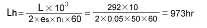
The lifespan(Ln) of a linear bearing in hours can be obtained by calculating the traveling distance per unit time. The lifespan can be obtained from the following equation if the stroke length and the number of strokes are constant:
|
 |
Lh: Lifespan(hr) S: Stroke length (m)
L: Rated life(km) n1: Number of strokes per minute (cpm) |
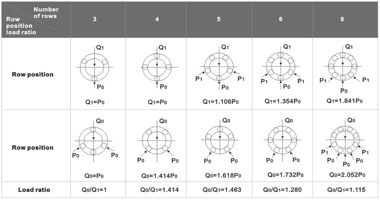
| Relation between ball circuits and load rating |
The IN'S linear bearing includes ball circuits that are spaced equally and circumferentially. The load rating varies according to the loaded position on the circumference.
The value the dimension table indicates the load rating when the load is placed on top of one ball circuit. If the IN'S linear bearing is used will two ball circuits loaded uniformly, the load rating will be greater. The following table shows the values by the number of ball circuits in such cases:
Table 1
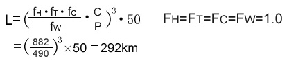
1. Obtaining the rated life L and lifespan Lh of the IN'S linear bearing used in the following conditions:
・Linear bearing: LM20
・Stroke length: 50mm
・Number of strokes per minute: 50mm
・Load per bush: 490N
The basic dynamic load rating of the linear bearing is 882N from the dimension table. From equation(1), therefore, the rated life L is obtained as follows:
From equation(2), the lifespan Lh is obtained as follows:
2.Selecting the linear bearing type satisfying the following conditions:
・Number of linear bearing used: 4
・Stroke length: 1m
・Traveling speed: 10m/min
・Number of strokes per minute: 5cpm
・Lifespan: 10,000hr
・Total load: 980N
From equation(2), the traveling distance within the lifespan is obtained as follows:
From equation(1), the basic dynamic load rating is obtained as follows:
Assume the following with a pair of shafts each with two linear bearings:
As a result, LM30 is selected from the dimension table as the IN'S linear bearing type satisfying the value of C
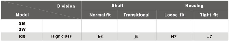
When a standard-type IN'S linear bearing is used with a shaft, inadequate clearance, adjustment may cause early bush failure and/or poor, rough traveling. The clearance adjustable linear bush and open linear bush can be clearance adjusted when assembled in the housing which can control the outside cylinder diameter. However, too much clearance adjustment increases the deformation of the outside cylinder,to affect its precision and life. Therefore, the appropriate clearance between the bush and shaft, and clearance between the bush and housing are required according to the application. Table 2 shows recommended fit of the bush:
Table2
Note: The clearance may be zero or negative. Please attention the movement.
To optimize performance of the IN'S linear bearing high precision of the shaft and housing is required.
1.Shaft
The rolling balls in the IN'S linear bearing are in point contact with the shaft surface. Therefore, the shaft dimensions, tolerance,surface finish, and hardness greatly affect the traveling performance of the bush. The shaft should be manufactured with due attention to the following points:
1) Since the surface finish critically affects smooth rolling of balls, grind the shaft at 1. 5 S or better
2) The best hardness of the shaft is HRC 60 to 64. Hardness less than HRC 60 decreases the life considerably, and hence reduces the permissible load. On the other hand, hardness over HRC 64 accelerates ball wear.
3) The shaft diameter for the clearance adjustable linear bush and open linear bush should as much as possible be of the lower value of the inscribed circle diameter in the specification table. Do not set the shaft diameter to the upper value.
4) Zero clearance or negative clearance increases the frictional resisiance slightly. If the negative clearance is too tight, the deformation of the outside cylinder will become larger, to shorten the bush life.
2. Housing
There is a wide range of housing differing in design, machining , and mounting. For the fitness and shapes of housings, see Table 2 and the following section on mounting.
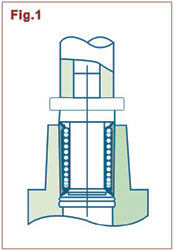
When inserting the linear bush into the housing. do not hit the linear bush on the side ring holding the retainer but apply the cylinder circumference with aproper jig and push the liner bush into the housing by hand or lightly knock it in. ( See Fig.1) In inserting the shaft after mounting the bush,be careful not to shock the balls. Note that if two shafts are used in parallel, the parallelism is the most important factor to assure the smooth linear movement. Take care in setting the shafts.
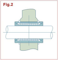
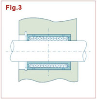
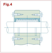
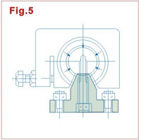
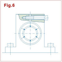
Examples of Mounting
The popular way to mount a linear bush is to operate it with an appropreiate interference. It is recommended, however, to make a loose fit in principle because otherwise precision is apt to be minimized. The following examples( Figs.2 to 6)show assembling of the inserted bush in terms of designing and mounting, for reference.
|
|
|